Code 001 3 4 bit Add-traction op. LIST OF FIGURES 11 TYPICAL DESIGN FLOW 3 22 Xilinx ISE Interface 9 31 32-bit Arithmetic unit 13 32 32-bit Logic unit 14 331 a 32-bit before Left Shift 15 b 32-bit after Left Shift 16 332 a 32-bit before Right Shift 16 b 32-bit after Right 16 333 32-bit Shift unit 17 34 Arithmetic Logic Unit 19 41 RTL of 32-bit ALU 44 42 4.
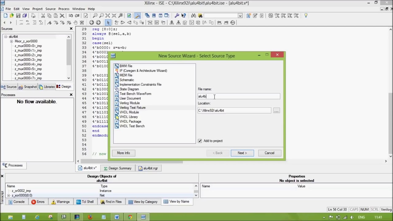
4 Bit Alu Design In Verilog Using Xilinx Simulator Youtube
Verified on Xilinx ISE simulator.
. Code 100 6 1s Complement of B op. VHDL Coding 22 10. ALUArithmetic Logic Unit is a digital circuit which does arithmetic and logical operations.
This research paper is based on the simulation of 16 bit ALU using VHDL. Design of 32-bit ALU 17 71. Functional Description of 4-bit Arithmetic Logic Unit.
The design was implemented using VHDL Xilinx Synthesis tool ISE and targeted for Spartan device. This is a 4 bit ALU that Adds and Substract4 Bit Full Adder -httpsyoutubeDVkbizPyde4. Design methodology has been changing from schematic design to HDL based design.
Bitwise OR 13 different operations are possible chosen based on a 4-bit selection code. 4 - bit ALU using Verilog. Verilog code for Clock divider on FPGA 33.
There are 6 different functions implemented in this ALU. Code 011 5 4 input NOR operation using dynamic NOR gate op. Each module of ALU is divided into smaller modules.
The codes are simulated in Xilinx ISE 131 to get the following waveform. 32-bit Arithmetic and Logical Unit 20 8. 1 4 bit Addition op.
Up to 24 cash back N-bit Adder Design in Verilog. Simulation Result for 4-bit ALU. Go to file.
Functions of ALU 21 9. Its a basic block in any processor. Since the output of the 4-bit ALU F30 is dependant on the signal M we have two ways of displaying our results.
N-bit Adder Design in Verilog 31. This paper presents design concept of 4-bit arithmetic and logic unit ALU. 32-bit Arithmetic Unit 17 72.
Explain by Examples 32. How to generate a clock enable signal in Verilog 34. Digital Clock manager DCM in Xilinx FPGA.
Mihir Gajjar and Mihir Gajjar 4 - bit ALU using Verilog. Include addition subtraction and shifting We proposed arithmetic and logic unit using VHDL structural and dataflow level design. In this Video you will learn how to design or implement the 4 bit ALU in verilog using Xilinx Simulator in very simple waySee Code here httpwww2dixco.
Controlled by the three function select inputs sel 2 to 0 ALU can perform all the 8 possible logic operations. Code 000 2 2s Complement of A op. Arithmetic and Logical operations included.
32-bit Shifter Unit 19 74. 4-bit ALU Design in Verilog HDL. Designed a 4-bit Arithmetic and Logical Unit ALU using Verilog HDL on Quartus II Web Edition.
An ALU performs following operations - Addition subtraction multiplication Not logical shift right logical shift left rotate right rotate left OR AND XOR NAND NOR. The arithmetic logic and shift units can be combined into ALU with common selection lines. Waveforms of Different Units of ALU 35 11.
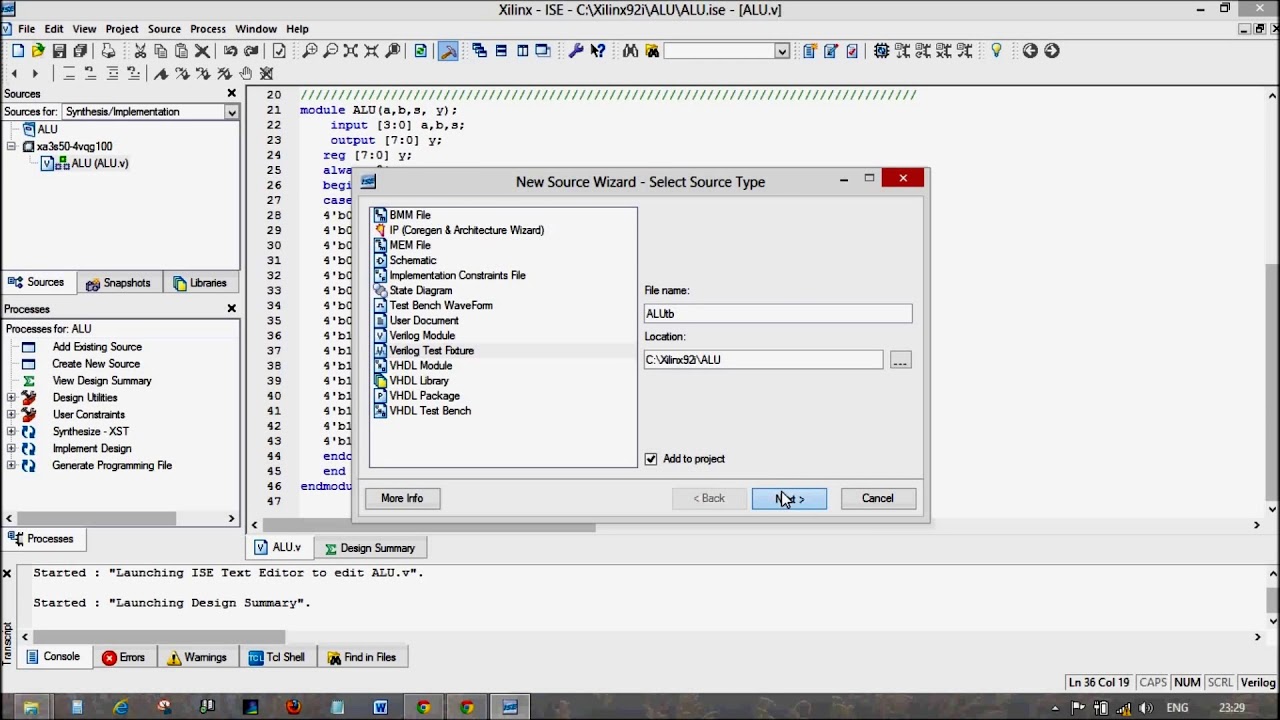
Arithmetic Logic Unit ALU is one of the most important digital logic components in CPUs. 4 bit ALU Design in verilog using Xilinx. Code 010 4 4 input NAND operation using static NAND gate op.
Click to share on Twitter Opens in new window. The testbench Verilog code for the ALU is also provided for simulation. This paper presents design concept of 4-bit arithmetic and logic unit ALU.
32-bit Logic Unit 18 73. All the modules in arithmetic and. Ac89774 on Mar 29 2017.

Xilinx Ise Full Adder 4 Bit Verilog Youtube
1

Verilog Code For Arithmetic Logic Unit Alu Fpga4student Com
4 Bit Alu Verilog
Alu Design In Verilog With Text Bench Youtube

Alu Design In Verilog With Testbench Simulation In Modelsim Arithmetic Logic Unit Youtube
1

Xilinx Ise 4 Bit Alu Add Subtract Verilog Youtube
0 comments
Post a Comment